Tim's 300W PTC Heating Plate.

I wanted a heating plate for soldering my PCBs with SMD components.
I have done a boring video just to show that it works using a PTC element.
There are many cheep PTC Heating Plates on the web for sale, so I went for a
300W one, it's dimensions are 9cm x 7cm. this is a nice size for the projects
I do.

PTC heaters are very efficient, the advert stated, after about 30 seconds it
will reach about 260 degree Celsius.
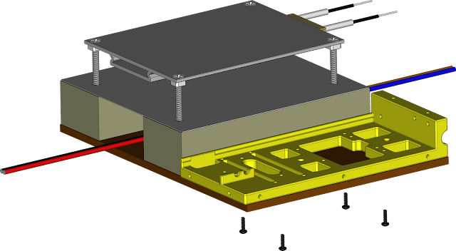
The picture above is upside down, on the topside you can't see in this
picture, the holes need countersinking.
What is PTC? Positive Temperature Coefficient
A PTC, or semiconductor, is a ceramic-based electrical component with temperature-dependent resistance that is used as a heating element. Its positive temperature coefficient allows electrical current to flow better at low temperatures than at high temperatures.
As the temperature rises, the PTC’s natural resistance increases while its
current conductivity and power output decrease until a state of equilibrium
is reached and the current can barely flow anymore. That’s the so-called PTC
effect.
Thanks to their self-regulating characteristic, PTC heating elements cannot
overheat, which makes this heating technology particularly safe and
reliable.
Because the resistance of one of these types of heater is not constant, the control of the temperature cannot be done by changing the power voltage.
Because the resistance of one of these types of heater is not constant, the control of the temperature cannot be done by changing the power voltage.
The only way to control the temperature is to turn it off when the required
temperature is reach, and turn it back on when the temperature falls below
the the required temperature.
Also as the resistance increases, there will be a maximum temperature this
type of heater will reach.
With this in mind I will be using a SSR (Solid State Relay) controlled by an
Arduino NANO.
Because the Arduino NANO will not be doing much, only checking temperature
and turning a relay on and off I will be using the AtMega168 version.


I have soldered leads direct to the power input of Arduino NANO, this will
leave room for other components. This lead will connect to the Power Bus.
Note! This is the 5 volt line for the Arduino NANO, make sure your power
supply for the Arduino NANO is not higher that 5 volt.

The hot plate was advertised at 300W, so W = vi, therefore Amps = 300
/ 240v = 1.25A.
For those countries on a lower voltage, say 110v, may need the G3MB-203P or
G3MB-205P version. 3 or 5 Amp versions. 300W / 110v = 2.7A, 400W / 110v =
3.6A
An alternative is this type of SSR. (Of the correct Amperage)

The first is controlled by a LOW Level Triger, the latter is controlled by a
HIGH Level Trigger.
I have gone for the cheapest as usual.
 This comes with a sheath and a screw connector. I don't need the screw
connector so I removed it.
This comes with a sheath and a screw connector. I don't need the screw
connector so I removed it.
Who thinks this blob on the end of the wires is the sensor bit?
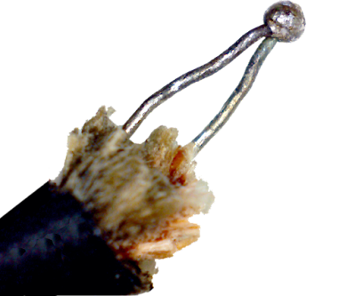
A weld has to be used because of the high temperatures this thermocouple is
used for.
If they were to be soldered together, the solder would melt at high
temperature and the connection would fail.
It is the actual wires that create the voltage that is measured to determine
the temperature.
So for those that have shortened these wire and thrown the offcuts away,
mistake, you can make another thermal couple with the offcuts. I will
explain.
This is a K-Type, so:
One wire is probably made of Alumel (approximately 95% nickel, 2% aluminium,
2% manganese, and 1% silicon).
One wire is probably made of Chromel (approximately 90% nickel and 10%
chromium).
 Both wire need to be insulated from each other. But if you heat the two
wires, the same amount of heat on each and the same length of wire on
each.
Both wire need to be insulated from each other. But if you heat the two
wires, the same amount of heat on each and the same length of wire on
each.
The voltage is small, so this is why we need a special device to measure the voltage and convert that voltage to a temperature. I will be using a MAX6675 Thermocouple Temperature Sensor Module to measure voltage produced by the K type Thermocouple.
Be carful buying the MAX6675, there is also a MAX31855.
The MAX31855 has Max voltage of 4 volt, the Arduino NANO has 5v logic pins.
This is why I use the MAX6675 it has Max voltage of 6v.
 You will notice that the MAX6675 has T+ and T-, this is important.
As I mentioned the Thermocouple acts like a battery so it has a positive and a negative wire.
 Also because I will be using a transformer to get 5 volt to power the Arduino
NANO, there will be a lot of noise, making it impossible to get a stable
reading, this is rectified by placing a 100uF capacitor to the negative side
of the thermocouple and ground (GND).
Also because I will be using a transformer to get 5 volt to power the Arduino
NANO, there will be a lot of noise, making it impossible to get a stable
reading, this is rectified by placing a 100uF capacitor to the negative side
of the thermocouple and ground (GND).
The two wires will act like a battery, the hotter the two wires are, the
higher the voltage.
Try the the above circuit with your offcuts and a voltmeter set to
millivolts. Just twist the ends together for this experiment.
What happens is:
When the wire is heated, it excites electrons inside the wire, the hotter
it is, the more electrons are excited.
The wires are made of different compositions so more electrons are excited
in one wire than the other.
Because the wires are connected at one end, this creates a differential
between the two.
The differential can be measured at the other open end of the wires
as a voltage.
The voltage is small, so this is why we need a special device to measure the voltage and convert that voltage to a temperature. I will be using a MAX6675 Thermocouple Temperature Sensor Module to measure voltage produced by the K type Thermocouple.
Be carful buying the MAX6675, there is also a MAX31855.
The MAX31855 has Max voltage of 4 volt, the Arduino NANO has 5v logic pins.
This is why I use the MAX6675 it has Max voltage of 6v.
As I mentioned the Thermocouple acts like a battery so it has a positive and a negative wire.
The MAX6675 needs to read the voltage the Thermocouple is producing the same
way a voltmeter does.
Usually the Thermocouple has red identification for the positive wire.
I have soldered wire direct to the MAX6675 Module with female DuPont
connectors to the open ends of the wires. I have kept the power wires
separate so that they connect to the Power Bus. The data connector will go
to the Arduino NANO.

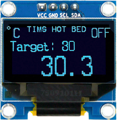
To view the temperature reading from the MAX6675 I am going to use a small
OLED display.
I will be using an 0.96 OLED 128X64 I2C SSD1306
To set the target temperature I will be using a rotary encoder with push
button.
Normally I attach these to a PCB so that I can add de-bounce RC (Resistor
capacitor) circuit to each switch, but in this case I will be adding
the resistors and capacitors to the actual encoder to save on space.

This is the circuit: Tims_Rotory_Encoder (G-V-A-B-S).pdf

I have made a plastic part on my 3D printer to mount these.
 This is the cover for all the components.
Here is the STL File: Cover.stl
I have soldered cables direct to these also, with the Power Cables kept
separate so that they will plug into the Power Bus, the other
cables connect to the Arduino NANO.

The OLED Display is fixed in place with four M1.7x6mm self tapping
screws.
Four plastic washers are used so that the screws do not stick out the other side.
Four plastic washers are used so that the screws do not stick out the other side.
Here is the STL File for the washers: M2_Washer_x_1.4_x_06.stl
To power the Arduino NANO from the mains, a small voltage transformer is
needed to get 5 volt.
I used the internals from an old Wall-Wart USB power supply.
But something like this will do:
 Dimensions are only: Length = 23.5mm Width = 18.1mm Height = 13.5mm
Search eBay for:
Mini AC-DC Power Supply.
Solder about 150mm of cable to the input and output.
I will also be adding a 5mm red LED that lights when the hot plate is to
hot to touch.


I have put a Female Dupont connecter to the positive side of the LED so it
can connect direct to one of the pins on the Arduino NANO. The other end
of the LED has a length of wire which will be connected to the common
(DC-) on the relay.
To support the hot plate I will be using wood as it is a good insulator
from the heat.
The base of the unit will be hardboard.
The components I will print plastic parts to mount them.
The Circuit
I have done a Fritzing to show how all the components are wired together.


Lets Start Putting it Together
The Base
The base I made from a piece of 3mm Thick hardboard, Width 108mm
Length 142mm.
This it to hold every thing together as one unit.
There are four 2mm diameter holes and five 4mm diameter holes

Hot Bed Supports
The supports for the Hot Plate I have made from two pieces of wood. Width
30mm Height 20mm Length 100mm.
Each piece has two holes drilled all the way through 2.6mm to take 3mm
screws.


DC Power
Next it's time to fit the AC-DC Power Supply Unit to power the the Arduino NANO from the mains.
At this time solder on the input and output cables, both about 150mm long.

The Red and Black is 5 volt coming out the front.
The Blue and Brown is mains coming out the back.
As there are going to be a few components that require power I have
soldered two rows of Header Pins to the end of the 5 volt cable. One
Black, one Red.
Each row of Header Pins has 6, one extra just in case.
This makes a Power Bus for all the components to plug into.

All the Black pins are soldered together with copper wire and connected
to the Negative lead.
All the Red pins are soldered together with copper wire and connected to
the Positive lead.
The back side of the headers where it is all soldered together is
insulated using
UV Resin. (or cheap Ultra Violet Fingernail Lacquer)
This makes it easy to connect power to all the components.
Heat Insulation
Next is to add some insulation, this is two part.
The first part is is a piece of reflective card. What I have used is a lid
of a
foil cooking tray, make sure it's a shiny lid.


This is all that happens to the cotton, but I have found it a good
insulator. You could use some glass fibre, but as I am not sealing it in,
I would just end up with itchy skin every time I touched it.

Thermocouple
I decided to drill a little hole (2mm) for the thermocouple to sit in, as
I have mentioned the little blob on the end of the wires is not the actual
sensor, but it will conduct heat to the wires of what ever it is touching.
I drilled the hole on the edge, away from the ceramic heater inside the
aluminium.

The overall length is about 200mm long.
I glued the blob inside the hole with some
UV resin. (or cheap Ultra Violet Fingernail Lacquer)
Hot Plate
I then fitted the Hot Plate to the wood supports.
I screwed the Set Screws into the wood until the top of the screw head was
20mm up off the wood.
I then tightened the nuts under the Hot Plate to hold in place.
 I don't show it here (can't draw cotton wool), but the cotton wool
insulation is between the Hot Plate and the Shiny Card.
I don't show it here (can't draw cotton wool), but the cotton wool
insulation is between the Hot Plate and the Shiny Card.
Component Mount
I have made some some parts out of plastic on my 3D printer.
If you don't have a 3D printer then I leave it to you to find a suitable box
to place all the components in.
The first part is a Plastic Base for all the components to be mounted on.

Here is the STL File:
Component_Support.stl
This is fitted with four M1.7x6mm self tapping screws from underneath.
Mains Lead
I'll start from the back with the mains lead, here a 3 Amp terminal
block is required to connect all the mains wires together. This is held
in place with an M1.7x10mm self taping screw.

Here is the STL File for the Cable Clamp:
Cable_Clamp.stl
The wires are connected like so to the Terminal Block.
The wires are connected like so to the Terminal Block.

SSR (Solid State Relay) Module
The SSR Module is held in place with four M1.7x6mm self tapping screws and
four plastic washers.

The wires from the Mains and the Heater fix in the two terminals on the
right (SW1).
There is a cover shown in the next photo, this is held in place with two
M1.7x6mm self tapping screws.
Here is the STL File:
Cable_Cover.stl
The SSR Module will require three cables approximately 100mm long.
Two for power DC+ and DC- with a double female DuPont connecter that will
be connected to the Power Bus.
One for the trigger (CH1) with a single female DuPont connecter which will
connect to the Arduino NANO.
The loose wire from the capacitor and the LED connect to the negative
(DC-) of the SSR Module also.
Arduino and MAX6675

The Arduino NANO and the MAX6675 can be fitted. The back of the Arduino
NANO fits under lip on the plastic, the front of the Arduino NANO is held
in place with a M1.7x6mm self tapping screw.
The MAX6675 is held at the back by a lip on the plastic, the front should
just push down and clip into place under anther small lip. push the
MAX6675 up against the Arduino NANO so the terminals line up with the
plastic recesses.
Connections
Hopefully every thing now has got DuPont Plugs on the end of all the
wires, with the exception of the Thermocouple and the Capacitor.
Start by fixing the Red Wire of the Thermocouple the the Positive Terminal (T+) of the MAX6675.
Start by fixing the Red Wire of the Thermocouple the the Positive Terminal (T+) of the MAX6675.

Now it should be a mater of plugging everything onto the Arduino NANO and
the Power Bus.
Lets start with the Arduino NANO.

All the Power to the Power Bus.

The LED is held in place with just the connector to the Arduino NANO.
Cover
Once all connections are done, carefully arrange any wires as need to fit
the Cover, using five M1.7x6mm self tapping screws.
Knob
Here is the STL File for the Knob:
Knob.stl
Fit the knob to the Encoder.
Firmware
I have put all versions of the the firmware into a zip file, in this zip
file there is also a copy of XLoader for installing the HEX file of your
choice.
Here is the ZIP File:
Hot_Plate_Firm.zip
The choices are:Tims_Hot_Plate_WB_G3MB.hex = With bootloader for G3MB Solid State relay. (Low Level Trigger)
Tims_Hot_Plate_NB_G3MB.hex = No bootloader for G3MB Solid State relay. (Low Level Trigger)
Tims_Hot_Plate_WB_ALT.hex = With bootloader for Alternate Solid State relay. (High Level Trigger)
Tims_Hot_Plate_NB_ALT.hex = With bootloader for Alternate Solid State relay. (High Level Trigger)
Plug It In
Provided every thing has gone to plan, It is ready to be plugged into the
mains.

Setting The Temperature
To set the Temperature, just dial-in the Target Temperature rotating the
knob.
To quickly turn off the Temperature, set the Temperature to Zero, just
push in the knob.
A Tip on achieving a Target Temperature quickly. (High Temperatures)
The control of the Temperature is done using a PID algorithm, this type of
heater (PTC) heats up quickly, it wants to get to it's max temperature as
quick as it can.
If you set the Target Temperature your require straight away, it will tend
to over shoot, and take quite a while to settle down. (This heater cools
down quite slowly)
The best method is to initially set the Temperature 10 degrees less than
what you want.
When it over shoots this Initial Temperature, it will start to cool down
to the Initial temperature.
When it starts to cool down set the Target Temperature to the value you
want.
A video of my first soldering of SMD on a PCB
No comments:
Post a Comment