Tim's ESP32 R.O.V.

There was an earlier version that was as simple as it gets for making an ROV
with an ESP32-CAM.
This one has a couple of upgrades, it has a simple track system and has an arm
which can hook on to things.
Components
ESP32-CAM and ESP32-CAM-MB
The main module for this is an ESP32-CAM Module.
You can now get an ESP32-CAM-MB (Mother Board) to easaly program this
module.


Take a look at what you are buying when getting Mother Board, one of
the above MB has only one switch, or the ESP32-CAM for that matter, there
are several manufacturers of these Modules.
Check what camera comes with the module, the cameras orientation cannot be changed with firmware, it is fixed. I have done a blog on how to change the cameras orientation if needed,
Check what camera comes with the module, the cameras orientation cannot be changed with firmware, it is fixed. I have done a blog on how to change the cameras orientation if needed,
Before the release of the Mother Board, you needed an FTDI programmer to
upload your code.

Before I continue I want to talk about power to the ESP32-CAM, when the
Camera is on it needs a lot of power. Depending on which FTDI Programmer
you have to program the ESP32-CAM, you may need to use a separate Power
supply for the ESP32-CAM, this ensures no brownouts after programming.
The Programmer I have has a jumper to switch the VCC between 3.3v and 5v,
this does not change the voltage on the Data Pins, these remain at 3.3v.
On this Programmer the 3.3v comes from the FTDI Chip and does not have
enough current to run the Camera.
So the jumper needs to be on 5v, this comes from the USB so the VCC is
connected to the 5v on the ESP32-CAM.

The new Motherboard supplies USB 5v to the 5v Pin..
To program the ESP32-CAM, GPIO Pin IO0 needs to be connected to GND when
Reset.
Some Motherboards have a switch for this.
I have done a small Modification to make it easy for those that don't have
the switch.
I have soldered a small SMD Switch across the two pins.
 I used to just put a jumper on these two pins when using the FTDI
Programmer, but that cant be done with the Motherboard with only one switch.
Without the modification you have to unplug the USB and plug it back in.
I used to just put a jumper on these two pins when using the FTDI
Programmer, but that cant be done with the Motherboard with only one switch.
Without the modification you have to unplug the USB and plug it back in.
About the Motherboards, I have found that I can program and run the Serial
Monitor with the ESP32-CAM Modules that came with the Motherboards, the
older ESP32-CAM Modules that did not come with the Motherboards, I can only
program, I cannot see the Serial from the ESP32-CAM Modules and the program
does not run until I remove the ESP32-CAM Module from the Motherboard.
The Arduino code is in this ZIP File:
ESP32-Cam_ROV_P.zip
The Arduino code has some options for how you want to Connect with Wi-Fi and
which Camera Module you use.
Read the comments inside the code to set the correct choices.
I have put lots of comments in the code so you can see what does what.
Motors and Diver
The motors are the cheep Motor with Gears found by searching for: intelligent smart robot car.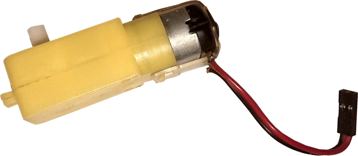
Add about 70mm of cable with Female Dupont connectors on the end to the
Motors.

For example:
At the time of writing, two motors where advertised at £5.50 (no wheels), the kit was only £7.90 (has wheels and battery holder).
If you don't have a 3D printer, you could use this kit as a base for this type of project.
The driver for the motors will be a
DRV8833 Module.
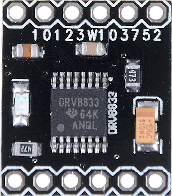
This is a 2 Channel DC Motor Driver Module Board 1.5A 3V-10V
I am using this driver because it uses less control pins (only 4) from
the ESP32-CAM.
PWM Control of Motor Speed
| xIN1 | xIN2 | FUNCTION |
|---|---|---|
| PWM | 0 | Forward PWM, fast decay |
| 1 | PWM | Forward PWM, slow decay |
| 0 | PWM | Reverse PWM, fast decay |
| PWM | 1 | Reverse PWM, slow decay |
I like to colour-code the header pins, this helps me get it right when
connecting things together.

Battery

I use these flat type because they are cheaper than the round bullet type
and they fit better into projects.
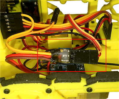
Buck
I will be using a Step-Up DC-DC Buck to increase the voltage of the
battery to 5v.
I found this
Small DC-DC Step-Up Adjustable SX1308 2A module.
 I have soldered wires direct to this module.

When soldering the battery wires to it, I kept the top right hole as it is
shown open, so that I can fix the module in place with a small screw.

The above is laid out like it should be made. There is about 50mm of cable
both sides of SX1308 Buck.

The Servo I am using is an
SG90 Micro Servo
with a single Horn
.
.


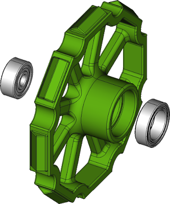
Hardware
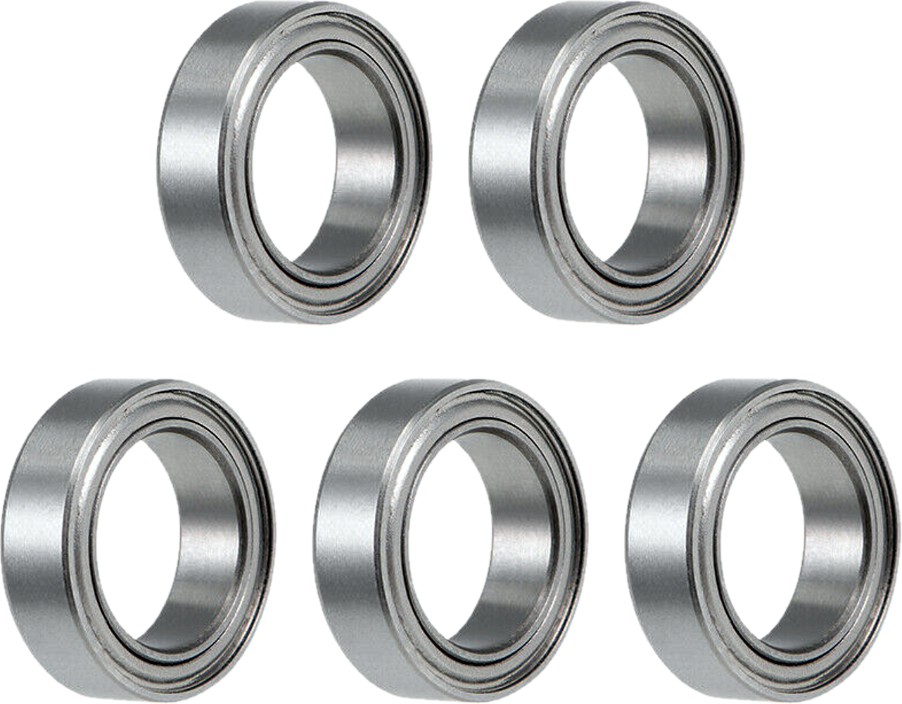
Two
Bearings: ID = 3mm OD = 10mm W = 4mm.

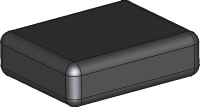


A
Small Weight.
Width = 35mm, Length = 40mm, Height =12mm.
The weight is not essential if you just want the R.O.V. to just run
around, I add the weight so that the R.O.V. has some mass when opening
doors with it's hook.
About 30
M1.7x6mm Self Tapping Screws.
Not essential, just to add a little grip to the treads on smooth floors
while pulling something.
The cable I use is four or three way
JR flat servo cable, There are many AWG sizes, I mostly use 22 or 26 AWG depending on the
price.
I find the four way is good for when I use I2C devices,


The back side of the headers where it is soldered to the cables
is insulated using UV Resin. (or cheap Ultra Violet Fingernail Lacquer)
is insulated using UV Resin. (or cheap Ultra Violet Fingernail Lacquer)
I start with a kit and refill it as needed.

Printed Parts
Frame.stl


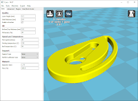

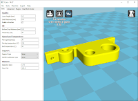


or


Tread_A.stl (X16)


Assembly
I will assume you have made/attached all the necessary cables and connectors to all the electronic modules as shown previously.
All screws will be M1.7x6mm Self tapping Screws unless stated.
Fit the Camera Mount Vertical to the
Base, with two screws.


Fit Hook Mount, with two screws.

Fit Servo to Servo Mount, with two screws.


Fit Servo Assembly to Base, with two screws.

Fit both Wheel Brackets to the Motors, with two M3x25mm Allen Cap Head Set Screws.


There is two versions of this, one has mount holes central, the other
has holes off-set, using the off-set version enables the slack to be
taken out of the track when it loosens with use.

Fit both Idle Wheels to the Rear Axle, use two M3x10mm Self Tapping Screws.


If you didn't get screws then two M1.7 may do.


Fit the DRV8833 Module with the
Motor Driver Bracket, use two screws.

Fit the SX1308 Module, using one screw.

Fit the Re-Set Bar. This just slides over the
Camera Mount Vertical.
Depending of the orientation of the ESP32-CAM, this aids pushing the
Re-Set Button if the Re-Set Button ends up at the bottom.

The ESP32-CAM Module should just slide inside the two
slots of the Camera Mount Vertical.
 Make up two sets of Track.
Each Track is made up of eight Tread A and
eight Tread B, with sixteen screws.
Make sure the Treads pivot around the screws, don't over
tighten the screws.
If you want to add foam pads to the treads, it is a good time to do this
now.
 Fit the Tracks to the R.O.V.
Easiest method is to remove the Drive Wheels, assemble and re-fit the Drive Wheels.
 Time to connect some cables.
It should be just a matter of plug things together if the cables shown
previously have been made.
Reference: Tims_ESP32-CAM_ROV_Power_Module.fzz, while connecting the cables from the SX1308 Module.

Bring the cables from the Motors up through the hole
between the two Battery Supports, plug them onto the DRV8833 Module.

and plug it onto the DRV8833 Module.
Make sure of the correct polarity.
Take the Cable DRV8833 IN1 & IN2, also the Cable DRV8833 IN3 & IN4 and plug these
onto the DRV8833 Module.

Next fit the Power Cable that goes to the
ESP32-CAM.
Then fit the Cables for POI 2, PIO 14, PIO 15 and
PIO 13 on the ESP32-CAM.

The Servo Plug goes to the Pins for the Servo.
It is best left unplugged until the first time it is switched on and has
been adjusted.
Instruction comes later.
Now fit the Battery.

First you will need to connect to the ESP32-CAM with your Wi-Fi device.
A Wi-Fi Device = Mobile Phone, Laptop, Tablet, PC or similar.
Depending on you choice of Wi-Fi connection in the Arduino Firmware.
The choices of Wi-Fi connection are:
- Access Point
- Local Network
"Access Point"
This is not connected to your local network, you connect to the Network of
the ESP32-CAM.
This means you can connect to it with your Mobile Wi-Fi Device any ware you are.
You change the Wi-Fi your Device is connected to, to the ESP32-CAM Wi-Fi.
Then open a browser on your Device to the IP of the ESP32-CAM control page. (may be
)
Have your serial monitor connected when you re-set the module to confirm correct IP Address.
"Access Point Password"
This is same as above, but you need a password to connect to the Wi-Fi.
It currently is: 2468
"Local Network"
This is, both you and the ESP32-CAM, connects to your local network.
You will need to give the SSID (name of your network) and the password required to gain access to your network.
You can connect to the ESP32-CAM from any devices browser that is connected to your network.
Open a browser to the IP of the ESP32-CAM control page. (may be 192.168.0.46)
Have your serial monitor connected when you re-set the module.
When connected with your web browser, the web page should look like this:
The LED Slider turns on the LED at a percentage of it's full power, it
does not go full power there is no need.
The LED is designed as a flash, so it should only be on full for brief
amount of time.
The Buttons do the movement, so the first test is to check that the motors
go in the right direction.
Push the Forward Button, check that both motors rotate forward.
If any of the Motor run in the wrong direction, then that motors plug
needs to turned around. This is the plug that is on the end of the cables
from the Motor.
The Speed Slider sets the speed at which it moves.
The Servo Slider moves the Arm up and down.
The Servo will probably need to be adjusted the first use.
Servo Adjustment
- Unscrew the screw holding the Servo Horn in place.
- Pull the Servo Horn away from the servo.
- Plug in the Servo Cables to the Servo Connector.
- Connect to the ESP32-CAM with your browser.
- Try the Slider for the Servo, the servo should move.
- Set the Servo to Zero Degrees.
- Re-Fit the Servo Horn so that the Servo Arm is in the following position.

You should be all set to go roving about with your Remotely Operated
Vehicle (R.O.V.)
To open and get through doors I made a little ring that can be fixed to
the bottom of the doors.

Here is the video again:
No comments:
Post a Comment